Simulate
RF simulation: FDTD and cascade
Run a full-wave FDTD of a layout on the GPU, drop vendor S-parameters and noise data into it, and read gain, noise figure, match and stability.
For RF work the usual split is two sims. An FDTD run of the passive board, with a port wherever an active part or a measured component sits, gives the board's S-parameters. A cascade then drops the vendor's S-parameters, noise and linearity data into those ports. Change the board and you rerun the FDTD; change a part and you rerun only the cascade, which takes seconds.
The LNA example is built this way, and this guide uses its files.
The FDTD run
name = "lna-rf"
layout = "lna"
cell = 0.1

[frequency]
start = "50MHz"
stop = "6GHz"
points = 596

[[ports]]
name = "IN"
pad = "J1.1"
reference = "In2.Cu"

[[ports]]
name = "AMP_IN"
pad = "U1.1"
reference = "In2.Cu"

[[ports]]
name = "AMP_OUT"
pad = "U1.3"
reference = "In2.Cu"
A port is a lumped port over a whole pad, down to the next copper layer or to the reference layer you name, 50 ohm unless it says otherwise. Copper is modelled as sheets on each copper layer: pads, tracks, vias as plated columns between the layers they span, and zone fills with their clearances. Dielectrics come from the stackup with their loss tangent. Capacitors, inductors and resistors take their schematic value as lumped parts by default; [[models]] overrides one with a value of your own, or leaves it open. Any other part is open.
Validated on a 50 ohm microstrip: return loss under -25 dB, insertion loss under 0.2 dB, and phase velocity within 1.2% of Kirschning-Jansen.
Size it before you run it
FDTD is expensive. The LNA's six port run took 27 minutes on a workstation GPU. Always dry-run first:
agentee sim lna-rf --dry-run{
"cells_millions": 4.202388,
"dt_fs": 120.43,
"grid": [335, 234, 55],
"runs": 6,
"max_steps": 150000
}That takes a second and says what the run will cost: one run per driven port, each over a grid of that many cells. To iterate:
- Start at
cell = 0.1and only tighten to the default 0.05 once the design has settled. The mesh grades out from copper edges, so the finest cell sets the cost. - Crop with
region = [x0, y0, x1, y1]to the part of the board the signal crosses. - Drive only the ports you need with
excite = ["IN"]. A cascade needs every port driven, so leaveexciteout there. - Run long sims in the background and keep editing other things. Check warns when a result has gone stale.
Run and read it
agentee sim lna-rf
agentee show sim:lna-rf
agentee render sim:lna-rf -o lna-rf.png
The run writes a .result.json and a Touchstone .s6p next to the spec, named after the spec file. show prints the readings, and render draws the magnitude plot and a Smith chart, as the viewer does.
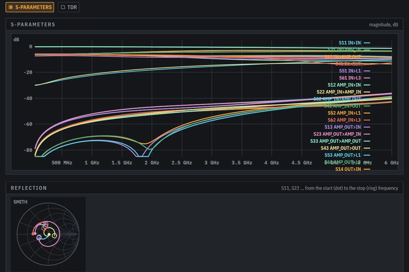
The result records a hash of the copper it saw (only the sim's region) and of the stackup. When either changes, check warns that the result is stale, and anything that reads it, a cascade or an interface measure, fails until you rerun.
The cascade
name = "lna-cascade"
kind = "cascade"
board = "lna-rf"
bandwidth = "2MHz"
report = ["900MHz", "1090MHz", "1.9GHz"]

[after]
nf = 6.0

[[devices]]
ref = "U1"
file = "models/qorvo_spf5189z.s2p"
ports = ["AMP_IN", "AMP_OUT"]

[[devices.datasheet]]
freq = "0.9GHz"
nf = 0.55
oip3 = 38.5
p1db = 22.4

[[devices]]
ref = "L1"
file = "models/coilcraft_bcr-162.s2p"
ports = ["L1"]
mount = "shunt"
Each device joins the board at its ports. A two-port amplifier takes its Touchstone file as measured; a two-terminal part takes the vendor's fixture data, mount = "shunt" or "series" as it was measured. The ports not joined to a device are the ports of the result.
Noise and linearity come along when the data is there: the Touchstone noise block when the file has one, the datasheet nf otherwise, and oip3 and p1db per frequency. [after] is the stage behind the output, a receiver with a 6 dB noise figure here, joined by Friis.
agentee sim lna-cascade
agentee show sim:lna-cascade
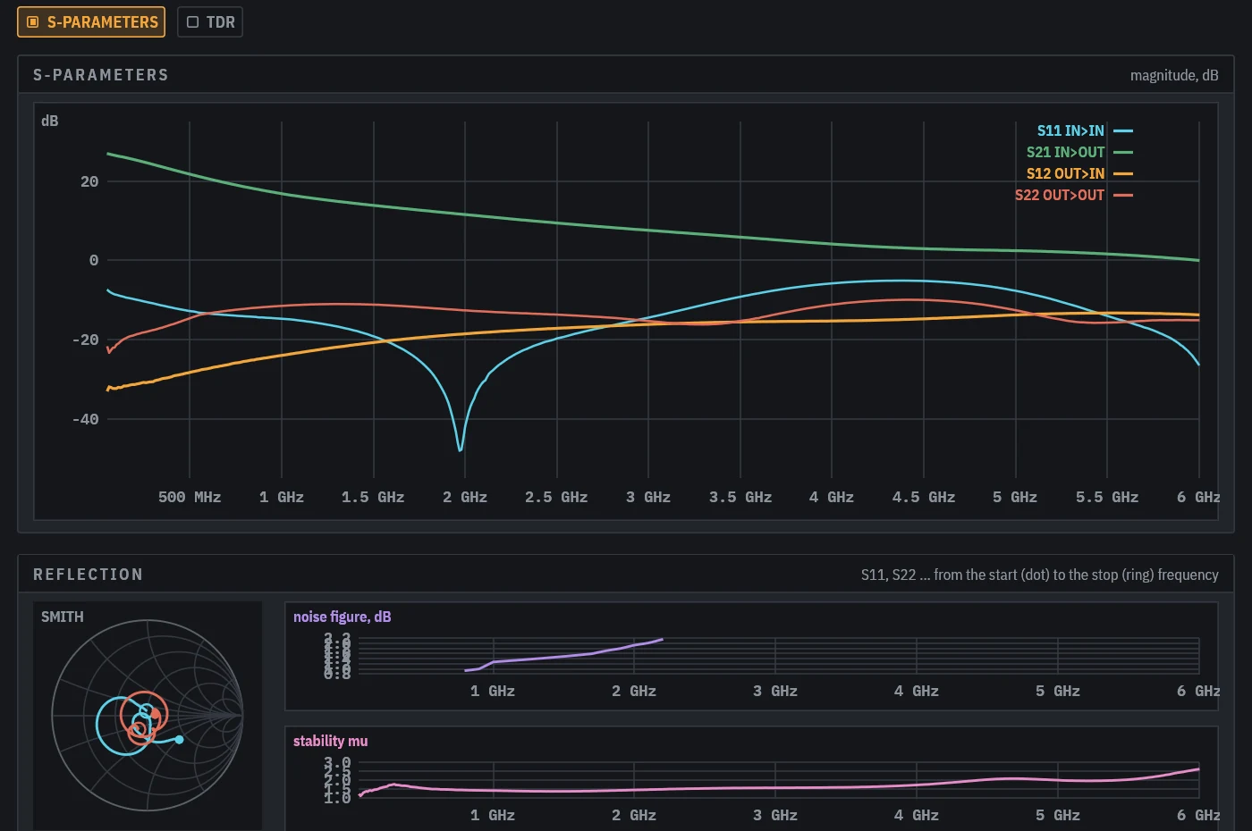
The readings for the LNA:
gain peak       27.0 dB    S21 at 50 MHz
input match     -5.1 dB    S11 at 4.380 GHz
output match    -9.9 dB    S22 at 4.420 GHz
stability mu    1.14       lowest at 60 MHz
noise figure    0.93 dB    best at 800 MHz, worst 2.16 dB at 2.200 GHz
at 900 MHz      gain 17.7 dB, NF 1.00 dB, floor -110.0 dBm, SFDR 86.8 dB, IIP3 20.3 dBm, P1dB out 21.9 dBm
at 1.090 GHz    gain 16.2 dB, NF 1.31 dB, floor -109.7 dBm, SFDR 87.9 dB, IIP3 22.2 dBm, P1dB out 21.9 dBm
Mu above 1 at every frequency means the amplifier is unconditionally stable on this board. The noise floor is -174 dBm/Hz plus the noise figure plus 10 log of the bandwidth, and SFDR is two thirds of IIP3 over the floor.
Where a device has no data, the band is cut to where every device has some, and a noise figure outside the data is left blank rather than guessed.
Post-process without rerunning
agentee sparam lna-rf --tdr IN --rise 50ps
agentee sparam link --pair 1,2,3,4
agentee sparam link --xtalk 1,3
sparam works on any FDTD or cascade result: a TDR of one port, mixed-mode S-parameters of a pair, and crosstalk in frequency and as a step. It always reports passivity and reciprocity when every port was driven. See Eye diagrams, PDN and S-parameters.
Fields and emissions
fields = ["1090MHz", "2.4GHz"]
far_field = true
An FDTD run can also record E and H field maps in the prepreg under the top layer, and the far field from a near-to-far transform, at up to four frequencies. The readings give the radiated power as a fraction of the input, the directivity, and the peak field at 3 m for 1 mW in, against FCC class B. Ports are matched loads, so cables and connectors are not part of the radiator.
Losses
Dielectric loss follows a causal Djordjevic-Sarkar model fitted to each layer's permittivity and loss tangent. Copper is a surface impedance that follows the skin effect, the stackup's roughness and, with finish = "ENIG", the gold and nickel on the outer pads, whose nickel adds several times the resistance of bare copper below a few GHz. The FDTD losses reference has the models and the measurements they were checked against.