Simulate
Logic simulation
Simulate the digital parts of a schematic straight from its netlist: 74 series models, stimulus, assertions, setup and hold checks, and a VCD out.
A logic sim runs the digital parts of a schematic straight from its netlist. No layout is needed, so it fits early in a design: check that a counter counts, a decoder decodes and an open-drain bus acknowledges, before anything is placed.
Start one
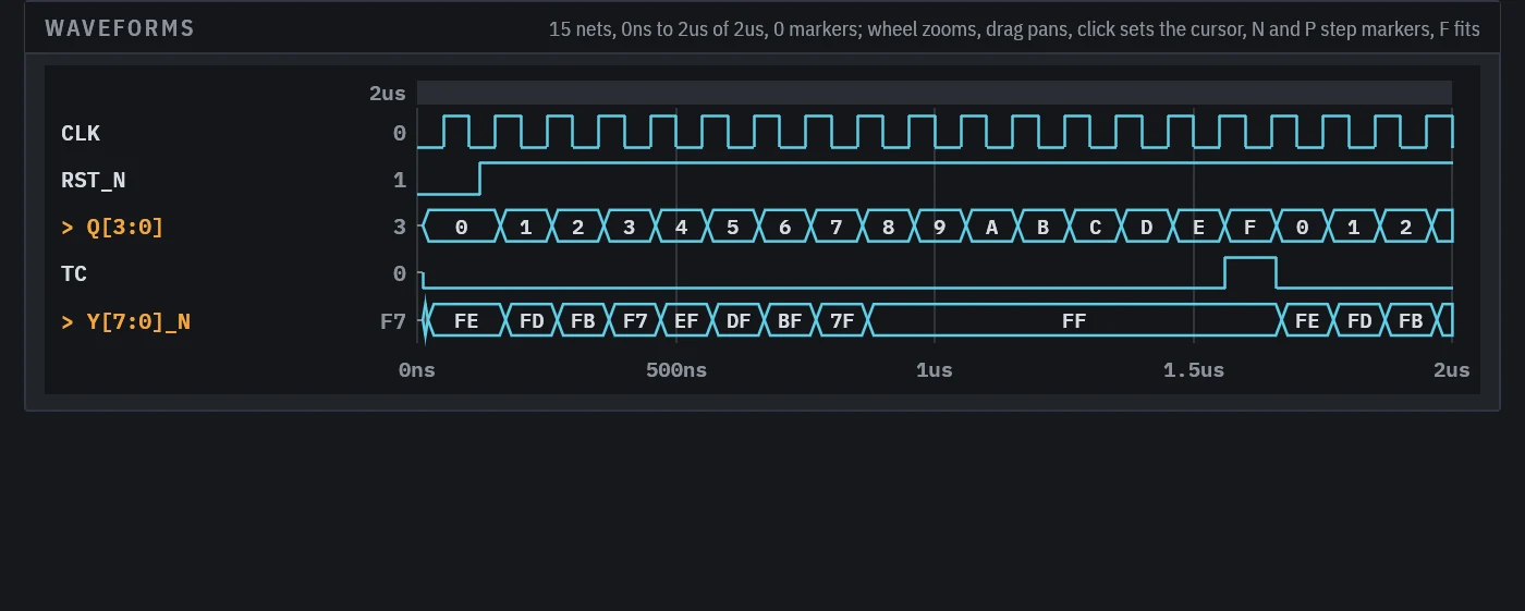
agentee new sim counter --kind logicThe starter has a clock, a reset and a clocked assertion to rename to your nets. The logic example holds two finished ones. This is counter, a 74HC161 counting a 10 MHz clock into a 74HC138:
name = "counter"
kind = "logic"
schematic = "counter"
duration = "2us"
ignore = ["J1", "J2"]
record = ["CLK", "RST_N", "Q3", "Q2", "Q1", "Q0", "TC"]

[[stimulus]]
net = "CLK"
clock = { period = "100ns", duty = 0.5, phase = "50ns" }

[[stimulus]]
net = "RST_N"
steps = [["0ns", 0], ["120ns", 1]]

[[expect]]
nets = ["Q3", "Q2", "Q1", "Q0"]
clock = "CLK"
edge = "rising"
sequence = [0, 0, 1, 2, 3, 4, 5, 6, 7, 8, 9, 10, 11, 12, 13, 14, 15, 0, 1, 2]

[[expect]]
nets = ["Y7_N", "Y6_N", "Y5_N", "Y4_N", "Y3_N", "Y2_N", "Y1_N", "Y0_N"]
at = "600ns"
value = "11011111"

[[expect]]
net = "TC"
at = "1600ns"
value = 1agentee sim counter
agentee show sim:counter
agentee render sim:counter -o counter.pngassertions passed 6 of 6
assertions failed 0
contention 0 strong drivers disagreeing
timing violations 0 setup, hold, recovery, removal
cells 5 18 nets
events 130 to 2usThe run writes a result and a VCD waveform next to the spec, which any waveform viewer opens.
Stimulus
- A
clockis low untilphase, then high fordutyof eachperiod. stepsare[time, level]pairs in time order, with levels 0, 1,"x"and"z".constantholds a net at one level.
A stimulus drives its net as a strong driver; on a supply net it replaces the rail.
Assertions
atreads a net or a bus once everything at that time has settled.- A
sequencereads the nets just before each clean edge of a clock, so a registered output is seen as it was when the edge came.fromskips the edges before it. - A bus value is a number or a string of
0,1,x,zand-for any, MSB first.
Check lists every failed assertion, contention or timing violation as an error on the sim, while the result is current.
What becomes a cell
- Power nets and power symbols are constant sources:
GND,VSS,VEEand0Vnames are 0, any other is 1. - 0 ohm resistors, jumpers and net ties join their nets. A resistor from a rail to a net is a pull-up or pull-down, a weak driver.
- Capacitors, inductors, diodes, LEDs, test points, crystals and the like are left out.
- Parts whose value or symbol name holds a 74 series number take a built-in model by pin number:
74HC00,SN74LVC1G08DBVRandCD74HCT04Eall match. The library covers the common gates, flip-flops, latches, buffers, the 138 decoder, the 161 and 163 counters, the 164 and 595 shift registers and the single and dual gate LVC parts. The open-drain parts pull low or let go. - A part whose value or symbol is a primitive name (
NAND,DFF,MUX2, ...) maps its pins by name. - Any other part is an error naming it, unless it is in
ignoreor has a[[parts]]model.
The family letters set the timing: HC is 10 ns delay and 15 ns setup, LVC 4 ns and 3 ns, LS 15 ns and 20 ns, with recovery and removal from TI and Nexperia datasheets. The logic reference has the full table and its sources.
Models of your own
[[parts]]
ref = "U7"
primitive = "nand"
pins = { A = "1", B = "2", Y = "3" }
delay = "3ns"

[[parts]]
ref = "U9"
inputs = ["1", "2", "3"]
outputs = ["4"]
truth = ["000 1", "1-- 0", "01- z"]
A part gets a primitive with its pins mapped, a library pinout borrowed with primitive = "74HC244", or a truth table whose first matching row wins.
Timing violations
Flip-flops, counters and shift registers check setup and hold on their clocked inputs, and recovery and removal on their asynchronous resets. On a violation the cell goes to x, as Verilog models do, until it is clocked or reset cleanly again. on_violation = "keep" reports the violation and keeps the sampled value instead.
The engine keeps four levels, 0, 1, x and z. Strong drivers that disagree give x and a contention; pulls count only when no strong driver is on. A gate goes to x only when the unknown input matters, so 0 into an AND is still 0.
In an interface
A logic sim can be a measure of an interface, which then fails check while the sim has a failure:
[[interfaces.measure]]
sim = "i2c-bus"